Introduction
The cope cage design evolution from improvised field welds to precision factory-standard fabrication represents one of the most rapid armor development cycles in modern military history. What began in early 2022 as hastily welded steel bars on Russian tanks has matured into a sophisticated engineering discipline encompassing structural analysis, ballistic simulation, and optimized production tolerances. This guide traces the complete cope cage design evolution across four distinct generations, examines how modern designs differ from early prototypes, and provides actionable insight for defense procurement officers, armored vehicle manufacturers, and fabrication engineers seeking to understand or specify cope cage armor systems.
The Russo-Ukrainian war fundamentally changed the trajectory of cope cage design evolution. The sudden proliferation of loitering munitions, FPV drones, and top-attack anti-tank weapons forced both sides to improvise overhead protection solutions practically overnight. From those field expedients emerged a new category of armored vehicle protection that is now being standardized by manufacturers worldwide. Understanding this evolution is essential for anyone involved in military vehicle protection, cope cage fabrication, or defense procurement.
The Origins — Field-Welded Cope Cages in the Russo-Ukrainian War
Early Prototypes and Improvised Solutions
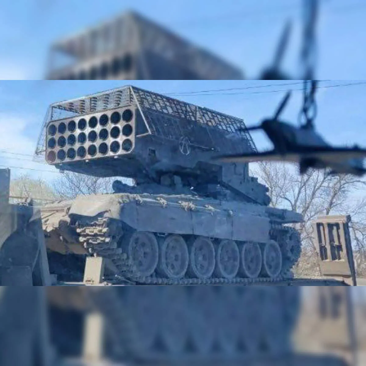
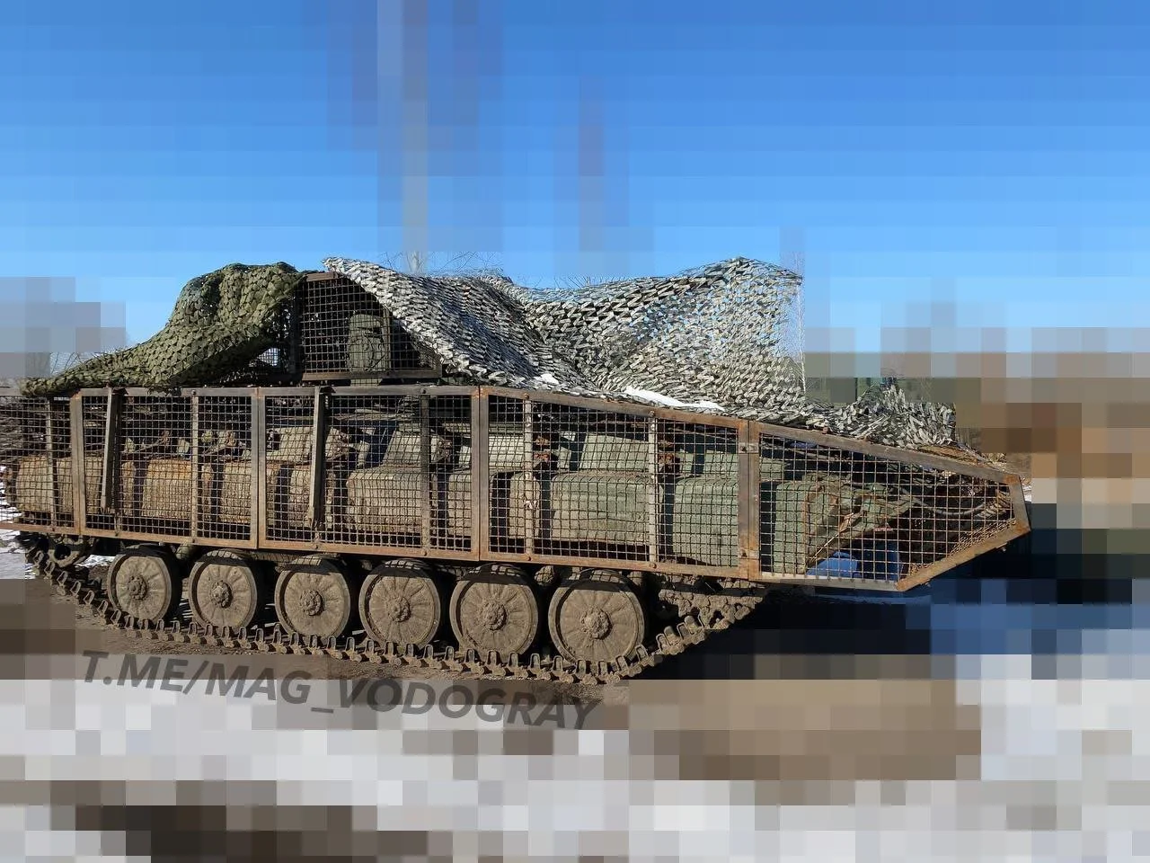
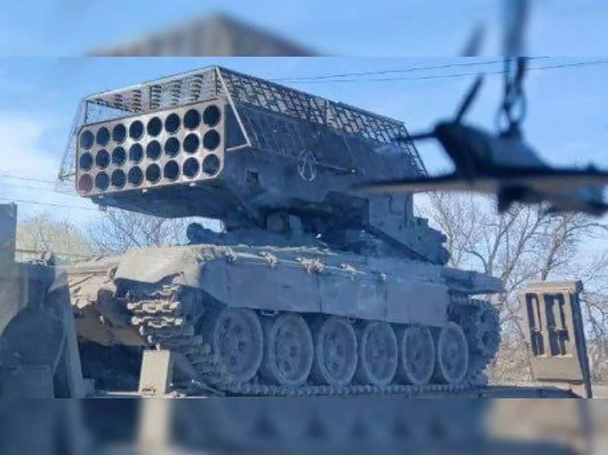
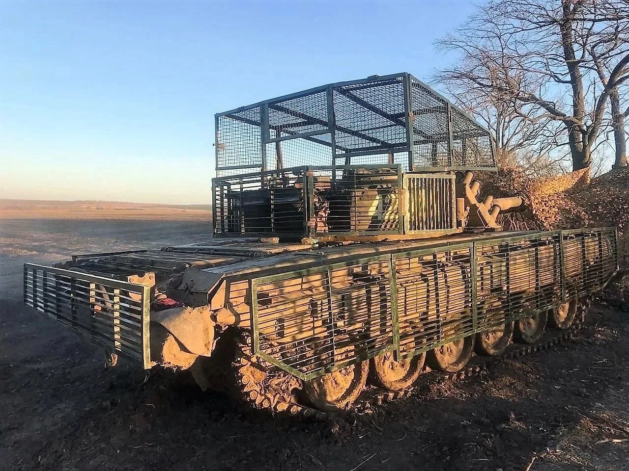
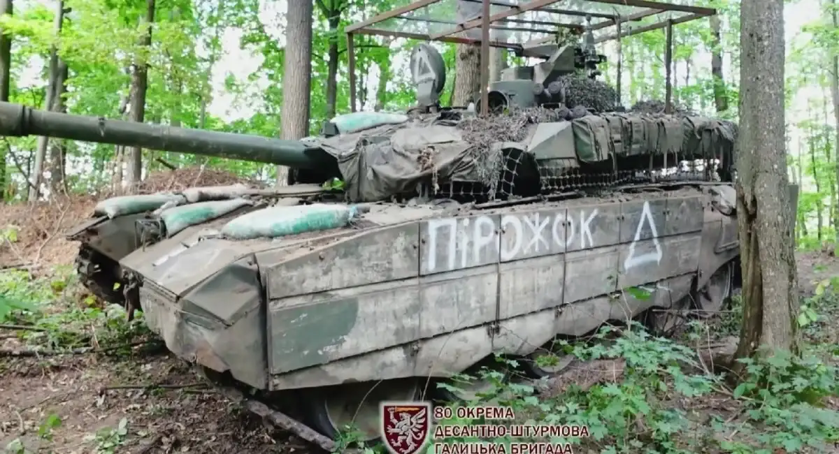
The earliest cope cages appeared on Russian tanks in the spring of 2022 as a direct response to drone-dropped munitions and Javelin top-attack missiles. These first prototypes were crude by any engineering standard — steel bed frames, rebar, and scrap metal welded directly onto turret roofs with no structural analysis, no weight calculation, and no consideration of vehicle mobility impact. Crews in the field used whatever steel they could find, creating highly variable protection that sometimes did more harm than good by blocking hatches or adding dangerous overhang.
Ukrainian forces quickly followed suit, adapting their own cope cage solutions using similar field-welding techniques. The early designs shared common limitations: inconsistent weld quality, no standoff optimization, excessive weight, and poor aerodynamic profile. Yet despite these shortcomings, these improvised cages proved effective enough against light munitions to justify further development. The battlefield data collected during this period became the foundation for the entire cope cage design evolution that followed.
First-Generation Design Characteristics
First-generation cope cages, field-welded throughout 2022, exhibited several defining characteristics that modern designs have since addressed. The slat spacing was inconsistent, ranging from 50mm to 150mm gaps with no deliberate calculation of shaped-charge jet disruption. Weld joints lacked reinforcement, and many failed under vehicle vibration or multiple impacts. Steel grades were unverified — often structural mild steel rather than armor-grade material — resulting in unpredictable ballistic performance.
Weight distribution was another critical flaw. Early cages concentrated mass directly above the turret center, raising the vehicle center of gravity and degrading cross-country handling. These issues underscored the need for professional engineering input, setting the stage for the next phases of cope cage design evolution where cope cage welding specifications and structural integrity became formal requirements.
The Four Generations of Cope Cage Design Evolution
The cope cage design evolution can be clearly mapped across four distinct generations, each representing a leap in engineering sophistication, manufacturing quality, and battlefield effectiveness. Understanding these generations helps procurement teams evaluate suppliers and helps engineers benchmark their own designs against industry progression.
First Generation — Field Weld (2022)
As described above, the first generation relied entirely on field improvisation. No CAD models, no production drawings, no quality control. Welding was performed by vehicle crews or field maintenance units using whatever equipment was available. Cope cage welding specifications were nonexistent. These cages served their purpose as emergency measures but were never intended for long-term deployment or manufacturing at scale.
Second Generation — Reinforced Frame (2023)
By early 2023, both military workshops and small fabrication shops began producing purpose-built cope cages. The second generation introduced reinforced perimeter frames—typically 40×40mm or 50×50mm square tubing—with welded cross-bracing to improve structural rigidity. Steel selection improved to known grades such as S355JR or equivalent structural steel. Weld specifications became documented, with 3-4mm fillet welds recommended for primary structural joints. These designs still lacked formal engineering analysis but represented a significant step toward standardization.
Third Generation — Modular Panel (2024)
The third generation marked the transition to modular, bolt-together panel systems. Instead of a monolithic welded structure, cope cages were designed as individual slat panels that could be assembled, disassembled, and replaced independently. This approach simplified logistics—damaged panels could be swapped in the field without cutting torches or heavy welding equipment. Modular designs also enabled vehicle-specific adaptation; the same base panel design could be configured for T-72, M1 Abrams, or BMP platforms by adjusting mounting brackets and panel count. CAD software became integral to this generation, enabling precise slat geometry and bolt-hole alignment with cope cage armor production tolerances of ±2mm on critical dimensions.
Fourth Generation — Factory Standard (2025)
The current and most advanced generation represents true factory-standard integration. Fourth-generation cope cages are designed concurrently with the vehicle platform itself, not retrofitted afterward. They incorporate jig-welded frames, robotic weld seams, CNC-bent slats, and pre-drilled mounting patterns verified against 3D laser scanning of the host vehicle. Armor-grade steel such as Armox 500 or Hardox 450 is specified, and full ballistic certification is performed on production samples. The cope cage design evolution has moved from reactive improvisation to proactive engineering, with production tolerances held to ±0.5mm on mounting interfaces and weld quality verified by NDT (non-destructive testing).
Key Design Improvements for Drone Protection
The primary driver of cope cage design evolution has been the rapid advancement of drone warfare. First-person-view (FPV) drones, loitering munitions like the Lancet, and commercial quadcopters modified to drop grenades have forced continuous design iteration. Each improvement addresses specific vulnerabilities observed in real combat footage and after-action reports.
Slat Spacing and Standoff Optimization
One of the most critical design parameters is slat spacing. Early cages used whatever spacing was convenient; modern designs optimize spacing based on the shaped-charge warhead diameters in common use. The engineering principle is straightforward: slats must be close enough to disrupt or prematurely detonate a shaped charge jet before it reaches the main armor, but wide enough to avoid excessive weight and preserve crew visibility. Current best practice spaces slats at 60-80mm center-to-center for overhead protection, narrowing to 40-50mm for vertical panels facing likely attack angles.
Standoff distance—the gap between the cage and the vehicle hull—has similarly been optimized. Modern cope cage design evolution has established that 300-500mm standoff is needed for effective disruption of tandem-charge warheads, while 200-300mm suffices for single-stage HEAT warheads. This standoff also creates space for deformation without transferring impact energy directly to the vehicle armor.
Anti-Top-Attack Geometry
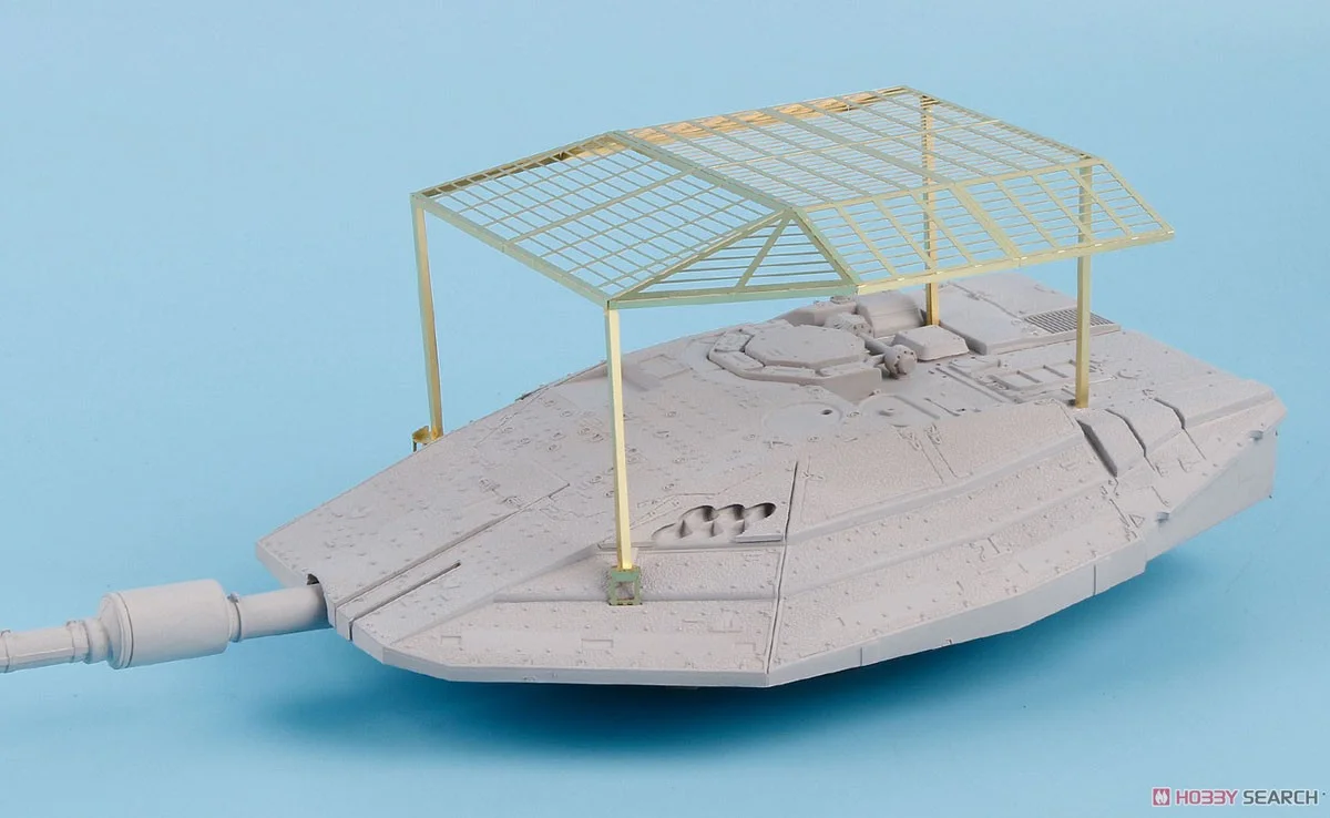
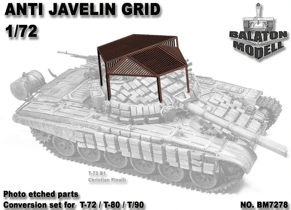
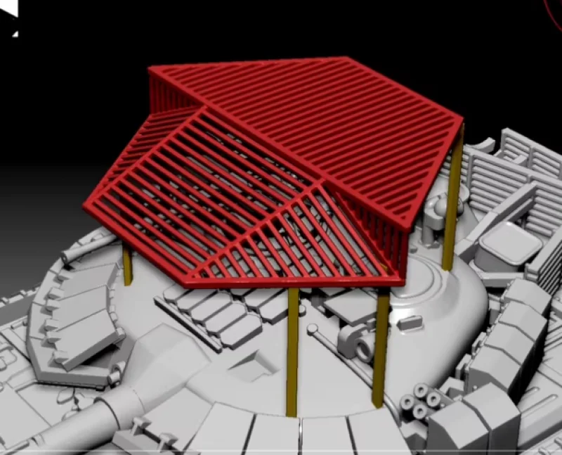
The most significant design improvement in recent generations is the adoption of anti-top-attack geometry. Modern cope cages are no longer flat horizontal screens but incorporate sloped, multi-angle surfaces designed to deflect, trap, or prematurely detonate munitions approaching from above. Common geometries include:
- V-shaped roof panels that deflect shaped charge jets away from the turret roof
- Extended side skirts that protect the vulnerable turret ring area from oblique top attacks
- Raised perimeter fencing that increases the effective standoff distance at the turret edges
- Double-layer slats with staggered offsets that create multiple disruption points for a single shaped charge jet
These geometric improvements represent a fundamental shift from the flat, single-plane cages of 2022 to the complex three-dimensional protection structures being fielded today. The integration of cope cage welding specifications with these complex geometries has driven adoption of robotic welding for consistent joint quality on multi-angle frames.
Design Variations Across Military Vehicles
No single cope cage design fits all platforms. The cope cage design evolution has produced increasingly vehicle-specific solutions that account for hull geometry, turret traverse arcs, crew access requirements, and weight distribution. Understanding these variations is critical for manufacturers and procurement teams evaluating cope cage solutions.
Tanks and Main Battle Vehicles
Main battle tanks (MBTs) such as the T-72, T-90, M1 Abrams, and Leopard 2 have the most complex cope cage requirements. Their turret roofs house critical optics, hatches, and ventilation grilles that cannot be obstructed. Tank-specific cope cage designs typically feature:
- Hinged forward sections that tilt up for driver hatch access
- Cutouts for commander and loader hatches with overlapping mini-cages that maintain protection while open
- Elevated standoff frames that clear the gunner panoramic sight and remote weapon stations
- Reinforced mounting brackets capable of supporting 300-500 kg without detaching under vehicle recoil or rough terrain
Tank cope cages also vary by threat environment. T-72 cages designed for Russian forces emphasize top-attack protection against loitering munitions, while M1 Abrams cope cages procured for export customers may prioritize FPV drone deflection and urban operations.
IFVs, Artillery, and Support Vehicles
Infantry fighting vehicles (IFVs) like the BMP-2, Bradley, and CV90 present different design challenges. Their lower profile and smaller turret footprint require more compact cope cage geometries. BMP cope cages, for instance, often integrate with the vehicle existing stowage baskets and ERA mounting points to avoid adding new structural penetrations.
Artillery systems such as self-propelled howitzers and towed guns require cope cages that cover the crew compartment while allowing the gun barrel to elevate and traverse without interference. These designs typically feature asymmetric coverage heavier protection over the crew cabin, lighter or no coverage over the engine deck. Truck-mounted systems and logistics vehicles use the lightest cope cage variants, often constructed from aluminum or thin-wall steel tubing to minimize payload impact.
For each platform type, cope cage armor production tolerances vary based on the complexity of the mounting interface. Simple flat-roof vehicles like trucks can tolerate ±3mm tolerances, while complex turret-mounted cages for MBTs demand ±0.5mm to ensure proper alignment with existing vehicle hardpoints.
CAD Software and Design Tools for Cope Cage Design
As the cope cage design evolution has progressed, the tools used to design these systems have become increasingly sophisticated. While early field-welded cages were designed by eye and welded by instinct, modern cope cage engineering relies on established CAD and FEA software platforms.
The most commonly used CAD software for cope cage armor design includes:
| Software | Application | Key Features for Cope Cages |
|---|---|---|
| SolidWorks | 3D parametric modeling | Sheet metal tools, weldment profiles, FEA integration |
| AutoCAD | 2D production drawings | Detailed weld callouts, dimensioning for production tolerances |
| Fusion 360 | Design + CAM integration | CNC path generation for bent slats, cloud collaboration |
| CATIA | Complex surface modeling | Advanced composite layup, vehicle platform integration |
| Ansys / Abaqus | FEA structural analysis | Impact simulation, weld joint stress analysis, weight optimization |
The typical design workflow begins with a 3D laser scan of the target vehicle to capture actual hull geometry including manufacturing deviations. Engineers then build a parametric cope cage model in SolidWorks or Fusion 360, iterating slat spacing, standoff distance, and mounting bracket positions. Production drawings are exported with GD&T (Geometric Dimensioning and Tolerancing) to control cope cage armor production tolerances during fabrication. FEA simulations verify structural integrity under vehicle vibration, blast overpressure, and impact loads before any steel is cut.
Welding Specifications and Production Tolerances
The shift from field improvisation to factory-standard fabrication has demanded formalization of cope cage welding specifications and cope cage armor production tolerances. These parameters define the difference between a cage that performs reliably and one that fails under combat conditions.
Cope Cage Welding Specifications
Professional cope cage welding specifications address several critical parameters:
- Weld type and size: Primary structural joints require 4-6mm fillet welds on both sides of each joint. Secondary connections may use 3mm fillet welds. Full-penetration butt welds are specified for load-bearing frame corners.
- Welding process: Gas Metal Arc Welding (GMAW/MIG) is preferred for production environments due to its speed and consistency. Shielded Metal Arc Welding (SMAW/stick) may be specified for field repairs. Robotic GMAW is standard for fourth-generation factory cages.
- Electrode and filler metal: ER70S-6 is the standard filler wire for mild steel cages. For armor-grade steel, matching austenitic stainless or low-hydrogen electrodes prevent hydrogen-induced cracking.
- Weld inspection: Production cages require visual inspection (VT) of 100% of welds, with magnetic particle inspection (MPI) or dye penetrant testing (DPT) on a statistical sample. Critical load-bearing welds on fourth-generation cages receive ultrasonic testing (UT).
- Preheat and interpass temperature: For steel thickness above 8mm, preheat of 100-150°C is specified to prevent cold cracking, particularly in winter deployment conditions.
Cope Cage Armor Production Tolerances
Production tolerances directly affect both fit and ballistic performance. The following tolerance classes have emerged through the cope cage design evolution:
| Parameter | Generation 1-2 | Generation 3 | Generation 4 (Factory Standard) |
|---|---|---|---|
| Slat spacing tolerance | ±10 mm | ±3 mm | ±1 mm |
| Mounting hole position | ±5 mm | ±2 mm | ±0.5 mm |
| Frame flatness | Not specified | ±5 mm | ±2 mm |
| Weld leg length | Not specified | ±2 mm | ±1 mm |
| Overall assembly envelope | ±20 mm | ±10 mm | ±3 mm |
These tightening tolerances are made possible by jig-based fabrication, CNC machining of mounting interfaces, and comprehensive quality management systems. For manufacturers transitioning from field-weld to factory-standard production, investing in proper welding jigs and inspection equipment is the most impactful step toward meeting these specifications.
Design Principles — Maximum Protection, Minimal Weight
Designing a cope cage that maximizes protection while minimizing weight is the central engineering challenge of modern cope cage engineering. The cope cage design evolution has progressively converged on a set of principles that balance these competing requirements.
Material Selection and Structural Analysis
Material choice is the foundation of weight-optimized cope cage design. The following material options present different trade-offs:
- Mild structural steel (S235JR-S355JR): Low cost, excellent weldability, widely available. Suitable for second-generation designs with moderate weight budget. Typical yield strength: 235-355 MPa.
- High-strength low-alloy steel (HSLA / S500-S700): Higher strength-to-weight ratio allows thinner sections for equivalent protection. Requires preheated welding and careful HAZ management. Typical yield strength: 500-700 MPa.
- Armor-grade steel (Armox 450/500, Hardox 450/500): Optimized for ballistic resistance with high hardness. More expensive and difficult to weld; requires specialized electrodes and post-weld heat treatment in some cases. Typical hardness: 450-500 HBW.
- Aluminum alloy (5083-H131, 7075-T6): Weight savings of 60% vs steel for equivalent structural strength. Lower ballistic resistance; typically used for vehicles where weight is critical and threat levels are lower.
Structural analysis using FEA software enables engineers to identify and eliminate unnecessary material. Frame members can be sized based on actual load paths rather than rule-of-thumb overbuilding. Modern cope cage designs typically achieve 15-25% weight reduction compared to equivalent first-generation welded structures through FEA-guided optimization alone, without any reduction in protective coverage.
Weight Optimization Strategies
Beyond material selection, several design strategies reduce weight while maintaining protection:
- Topology optimization: FEA-driven algorithms remove material from low-stress regions of the frame, creating organic-looking structures that use steel only where structurally needed.
- Variable slat density: Critical threat axes receive tighter slat spacing (50-60mm), while low-threat areas such as the rear deck may use wider spacing (100-120mm) or be left open entirely.
- Hybrid material construction: Combining steel frames with aluminum or polymer composite panels reduces topweight without compromising structural integrity. Some fourth-generation designs use steel perimeter frames with aluminum mesh infill.
- Minimalist mounting: Eliminating excess brackets and using shared mounting points reduces part count and weight. Bolt-in designs weigh 10-15% less than equivalent welded-on cages due to the elimination of backup bars and reinforcement plates.
For procurement teams, the key metric is the protection-to-weight ratio. A well-designed cope cage should add no more than 5-8% to the vehicle gross weight while stopping a defined threat set. Any design exceeding 10% weight addition should trigger a thorough weight reduction review before production release. Dengtai applies these principles across all our cope cage fabrication projects, ensuring each design meets threat requirements without compromising vehicle mobility.
Conclusion
The cope cage design evolution from field weld to factory standard is a powerful example of rapid, combat-driven engineering iteration. In just three years, cope cage armor has progressed from improvised scrap-metal solutions to precision-engineered, certified protection systems designed in CAD, fabricated to tight tolerances, and integrated with host vehicles at the factory level.
For defense procurement officers and armored vehicle manufacturers, the key takeaways are clear. First, specify formal cope cage welding specifications and production tolerances in every procurement — the days of accepting field-welded improvisation are over. Second, require CAD-based design and FEA validation to ensure structural integrity and weight optimization. Third, choose a fabrication partner with demonstrated capability across all four generations of cope cage technology, from field weld through factory standard.
Dengtai offers end-to-end cope cage fabrication services spanning design, prototyping, and production. Our engineering team works with SolidWorks, Fusion 360, and Ansys to deliver optimized designs, and our factory certifications include ISO 9001:2015 and weld procedure qualifications to AWS D1.1 standards. Contact us to discuss your specific vehicle platform and threat requirements.